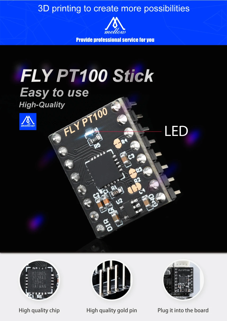
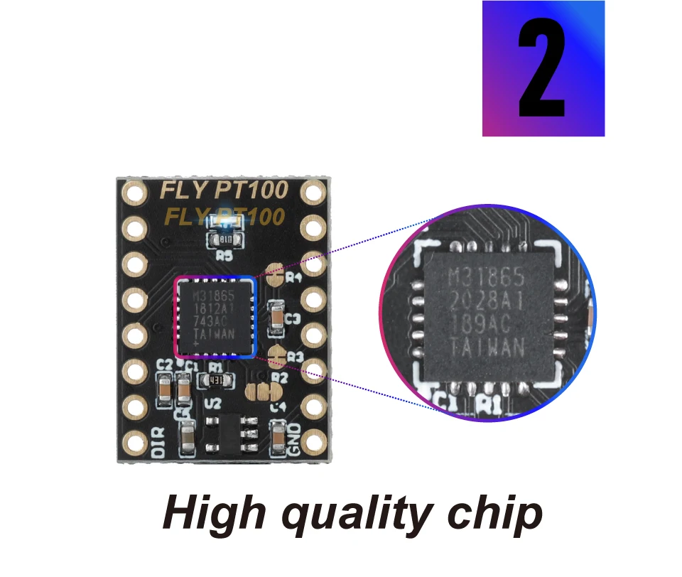
Raymond h designed the PT100 stick board.Please check more documentation from the Github repository.
The original version only supports 3.3V, we add 5V
This tutorial takes the Fly9 axis board as an example This module is only applicable to Marlin 2.0.7.2 and later
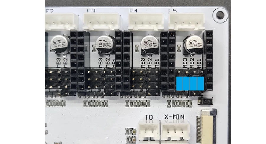
First, jumper the driver port to SPI mode
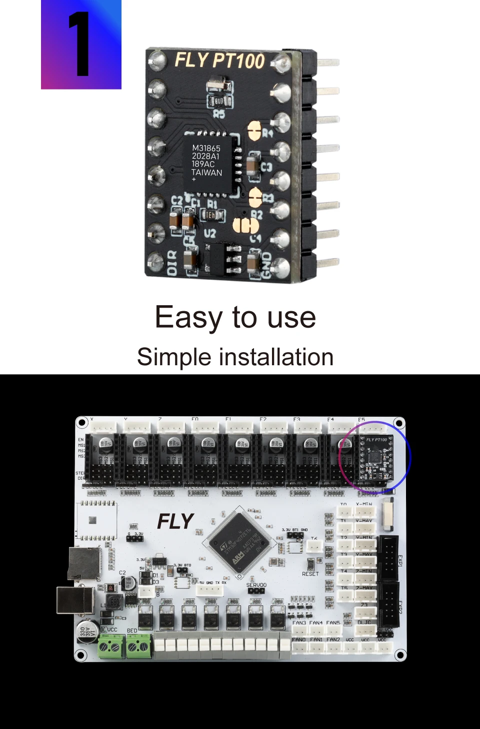
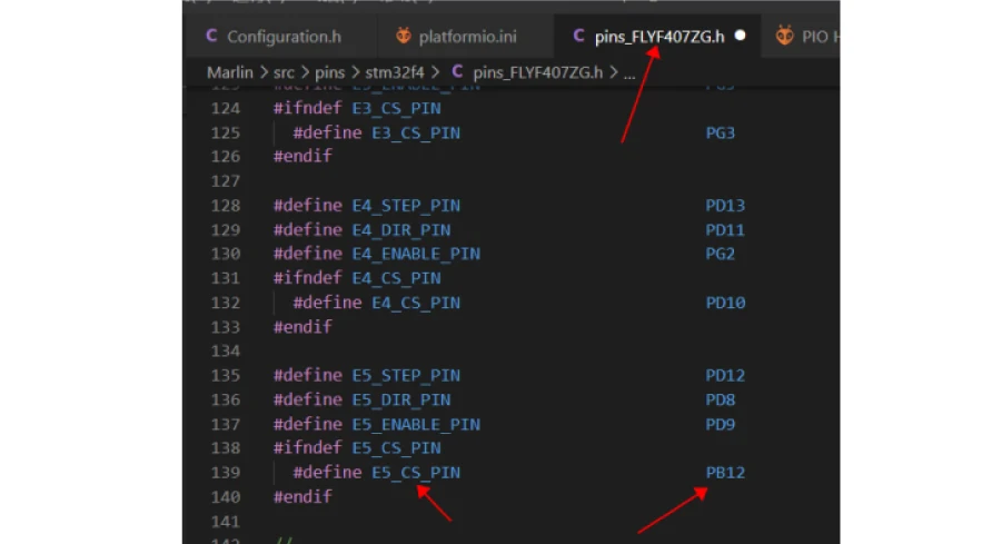
Take E5 drive port as an example
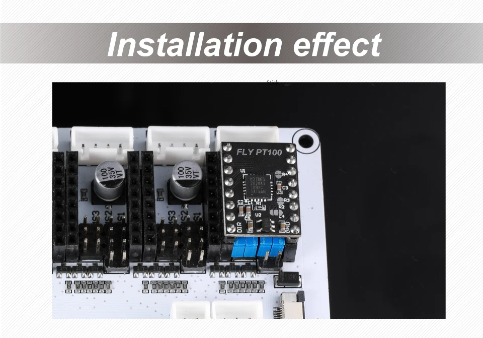
Insert the module into the driver port correctly:
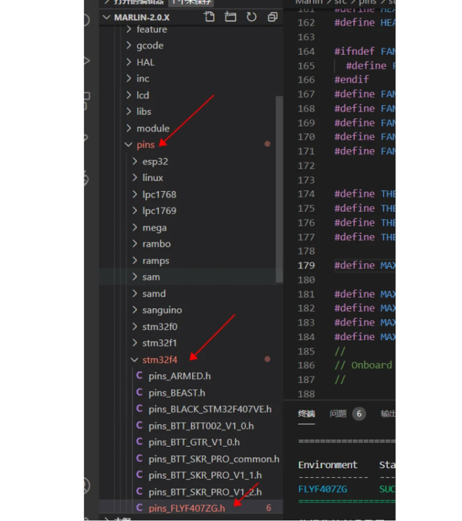
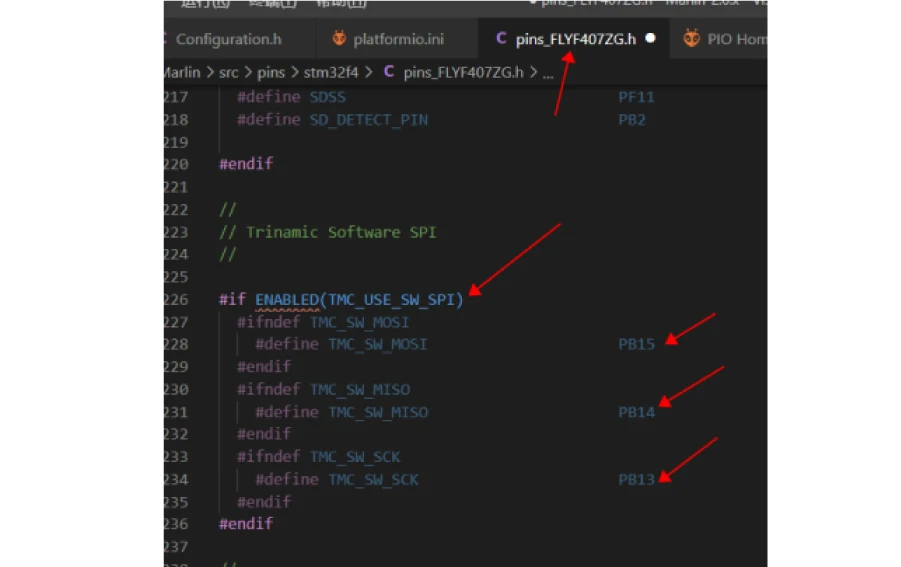
Open the firmware and find the corresponding Ping. H of the motherboard
Find the SPI mode pin definition corresponding to the motor
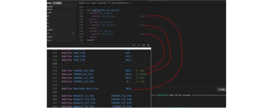
As shown in the figure, MoSi is pb15, MoSi is pb14 and SCK is Pb13
Find the CS corresponding to the drive port_ Pin, as shown in Figure E5
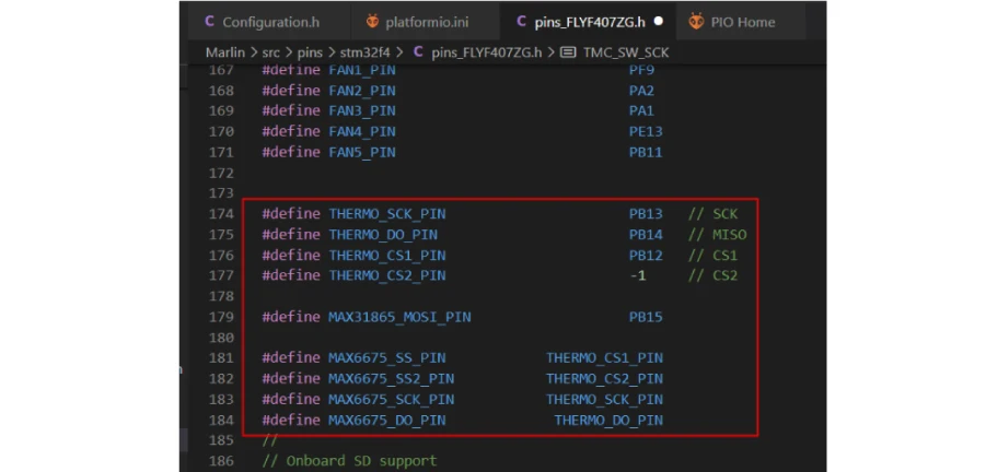
Then we define the module communication pins
#define THERMO_ SCK_ PIN PB13 // SCK
#define THERMO_ DO_ PIN PB14 // MISO
#define THERMO_ CS1_ PIN PB12 // CS1
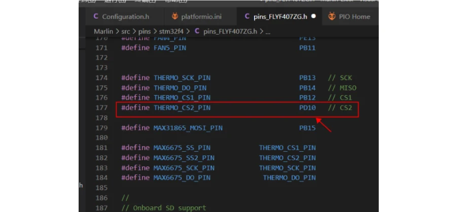
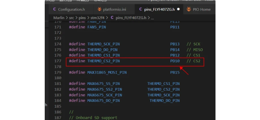
#define THERMO_ CS2_ PIN -1 // CS2
#define MAX31865_ MOSI_ PIN PB15
#define MAX6675_ SS_ PIN THERMO_ CS1_ PIN
#define MAX6675_ SS2_ PIN THERMO_ CS2_ PIN
#define MAX6675_ SCK_ PIN THERMO_ SCK_ PIN
#define MAX6675_ DO_ PIN THERMO_ DO_ PIN
See the diagram of this mainboard support for other mainboards
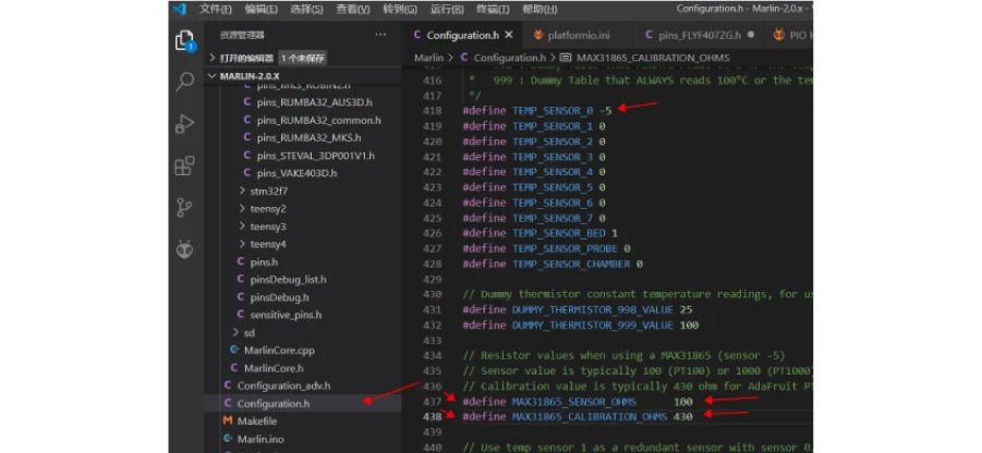
Then change the first nozzle thermistor model to - 5, and set it to PT100, and the sampling resistance is 430:
As shown in the figure below:
If you need 2 Pt100
For example, plug another one into port E4
Please plug E4 port jumper cap into SPI mode (same as E5)
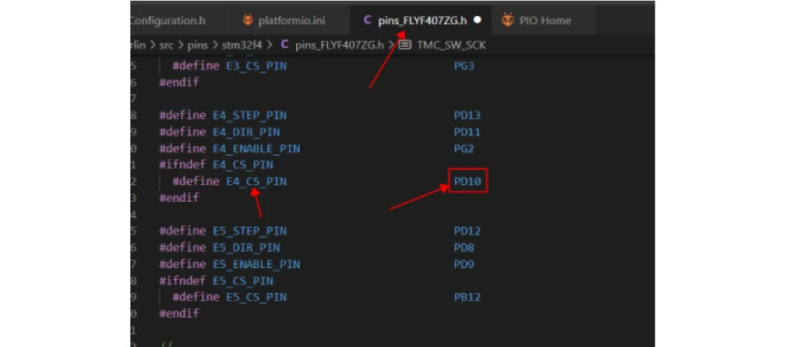
See E4 CS_ Pin pin:
CS2: communication module pin modification
After the setup is completed, the compiled firmware can be uploaded to the motherboard